Preface
If you haven’t been living under a rock you’ve probably heard about (Signed) Distance Fields when it comes to CG. Shadertoy is full of them and most everything points back to the work done by the legendary Íñigo Quílez.
An SDF is an extremely versatile data structure, as it can not only greatly aid in accelerating a Raymarch algorithm, but be used in things such as GPU particle simulations.
I’m not going to bother writing about setting up a Raymarcher with Signed Distance Functions since there are already a number of well-written articles on the subject. So if you’re looking to implement volume rendering, I humbly defer to one of those.
One thing these don’t seem to touch on, however, is getting anything more than compound primitives by way of boolean, union, and other modifiers. These are great for understanding how SDFs work but they are somewhat impractical beyond anything more than a demo scene. I want real-time speeds,1 and I want our artists to be able to easily convert from polygonal data to SDFs with little-to-no effort. 2
The obvious answer here is to precompute the Distance Fields and store them in a format that is easily read by the GPU, a Texture.
Precomputing SDFs
One thing I absolutely love in Unity are their ScriptableObject assets. For the SDFs I’ve opted to use those as a container which holds a sub-asset that is a Texture3D, since our SDFs will be 3D. The texture will be Linear RFloat as we really only need a single channel, but also need to support a signed float value. This results in a 32-bit float value which is the closest signed distance to a face, per 3D pixel.
To compute this, I reverse-engineered what Kosmonaut’s Blog accomplished over 2 in-depth blog entries. This as well as a couple whitepapers, which I am the first to admit that I am terrible at deciphering, served as my road map.
Basically, the algorithm looks like this:
foreach (pixel in texture)
    foreach (triangle in mesh)
         get pixel center as mesh bounds position
         get closest point on triangle
         calculate distance from pixel position to triangle
         keep the smallest distance
         perform a raycast along arbitrary vector against triangle
         if(raycast intersects triangle)
            increment an intersection counter
    if(number of intersections is even)
        pixel value is positive // outside mesh
    else
        pixel value is negative // inside mesh
This was implemented in a ComputeShader executed across 8x8x8 threads, so performance is quite good, even for a naive implementation. At this point, I haven’t decided to optimize further since SDF generation for Mesh data of even 100k triangles at an unnecessarily high texture resolution will only take a few seconds, including any GPU read back and IO hits. Once I revisit the algorithm, I’m confident that SDFs for Meshes of reasonable complexity could be computed in real-time, albeit at lower resolutions. That being said, a low resolution doesn’t necessarily equate to poor visual results, especially for things like raymarched soft shadows or subsurface approximation.

The ScriptableObject container here also gives us a place to store some important scaffolding data, such as bounds information, cell size, and scalar data for decoding the texture into world-space.

Using SDFs at Run-Time
There are a couple ways I’m expecting to use SDFs, a higher resolution local SDF and a coarse aggregate SDF for more global information. Unreal uses them in a couple different ways as well.
The local, fine (read: hi-rez) SDF has already been solved with my SDF Object. The coarse SDF is something that needs effort in solving.
Looking at other solutions for handling multiple instances, my options appear to be manage a 2D atlas of all the SDFs in a scene and then fetch them based on offsets, or try and aggregate all the data in a single 3D Texture. I’m choosing the later option for a couple of reasons: uniformity and hardware filtering.
On the subject of filtering, if I were to pack my SDFs as a 2D atlas, I would need to implement bilinear filtering in software, since I’d be packing the volume’s depth ‘slices’ along either the Texture’s x or y axis, whereas with a Texture3D I have this filtering by default. Filtering is so important to maintaining smooth results at low resolutions, so this is a point I will not concede unless I absolutely have to.

A brute-force implementation of coarse-level SDF aggregation should look something like this:
foreach (cell in Coarse Volume)
    foreach (fine SDF Volume in Scene)
        if(cell is inside the volume bounds)
            sample SDF Texture at cell point
            if(current cell value > SDF value)
                replace value in cell
        else
            calculate closest point on volume bounds
            sample SDF Texture at point on bounds
            add SDF value to distance to bounds
            if(current cell value > SDF value)
                replace value in cell
The naive approach is super inefficient since we’re cycling through every cell, to every volume, and possibly updating this every frame. This doesn’t concern me at this point because there are plenty of well documented algorithms to try speeding this up in the future (e.g. Octree, Spacial Hash, BVH). At this point, I’m much more concerned with getting something working.
Getting To The Bounds
First up is just working with bounds. I’ll assume an arbitrarily sized World-Space, Axis-Aligned Bounding Volume which will be composed of some arbitrary number of cells. For the sake of simplicity, I’ll concede that all cells are uniformly cubical.
Before I get into doing distances, I’ll just write colour. Iterating through every cell, deriving a bounds based on cell center and extents, I’ll then iterate through a collection of volumes that have arbitrary transformations. I’ll take the cell bounds’ min and max positions, transform them into the local space of the volume, and simply check if either point is contained in the volume’s bounds. Easy.
The result is as expected, some voxel-like cubes that make a lo-res representation of a couple arbitrarily transformed bounding boxes.

This is great, but I’m going be working with distance values in the end, and I’ll no doubt have a bit of ‘vacuum’ where cells don’t fall within a volume at all. In this case, I’ll take a page from what I’ve already done in order to compute an SDF from a Mesh and found the closest distance to the bounds of a volume.

At this point I can get the closest distance to any volume, which is *almost* everything I need to pull this off. The remaining problem is something that thankfully was already covered by Kosmonaut’s Blog: triangle inequality. I won’t rehash it since it’s already been summed up very well.
I set out to solve this based on sphere-sphere intersection, which I’ve got code for here:
 float3 n_i = s1 - s0; // the normal of the intersection
 float d = length(n_i);
 float h = 0.5 + (r0*r0 - r1*r1) / (2.0 * d * d);
 float3 c_i = s0 + h * (n_i); // center of the intersection circle
 float r_i = sqrt(abs(r0*r0 - h*h * d*d)); // the radius of the intersection circle
And running this with some Gizmos for visualization yields the expected behaviour:

After pulling all this into a ComputeShader, I’ve got coarse volume aggregation working. It’s not perfect, as I am observing a few artifacts which I am currently attempting to isolate. The first appears to be caused by the inherent point sample of the RWTexture3D. I may be able to double-buffer this to work around it, but that may eat up too much memory to really be worth it.

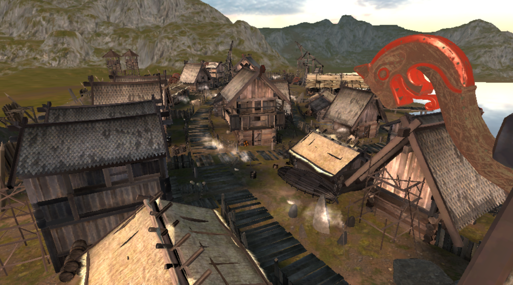
And across multiple resolutions:

Practical Uses
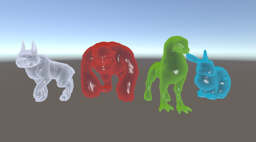
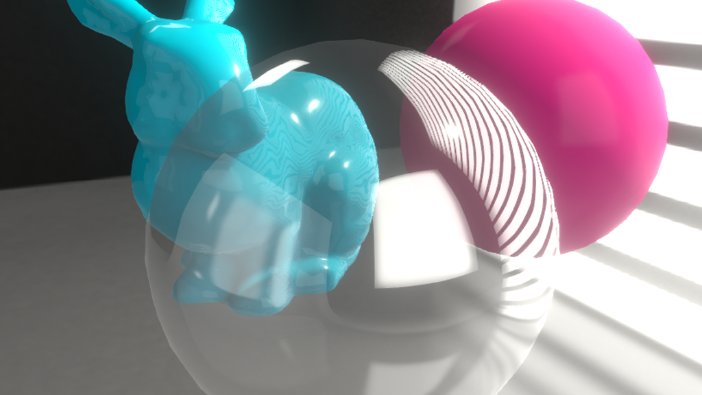
I managed to get subsurface scattering with the SDF working quite trivially, albeit very crudely:

Final Thoughts
This is all well and good, but there is a long way to go before this becomes viable in a project.
Some things to consider here on my next dive into this is that the coarse volume aggregation is possibly unnecessary and not really performance-friendly. On the other hand, it would only be modified at Editor-time, but I think a BVH with an atlas will do much better as it will likely allow for a more sparse data structure, and a lighter kernel. It’s an interesting theory, anyway.
Another thing is revisiting the actual SDF texture. I theorize that I can probably get 8-bits working just fine, or perhaps 16-bit, worst case. This should greatly improve performance as well.
I hope to have more time to chase this in the not-too-distant future.


